Kia Cadenza: Automatic Transaxle System / Automatic Transaxle Repair procedures
Kia Cadenza YG 2016-2025 Service Manual / Automatic Transaxle System / Automatic Transaxle System / Automatic Transaxle Repair procedures
| Removal |
| 1. |
Air cleaner assembly and air duct.
(Refer to Engine Mechanical System - "Air cleaner") |
| 2. |
Battery and battery tray.
(Refer to Engine Electrical System - "Battery") |
| 3. |
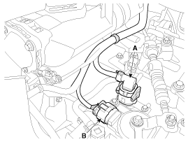
Dissconnect the solenoid valve connector (A) and inhibitor switch connector (B).
|
| 4. |
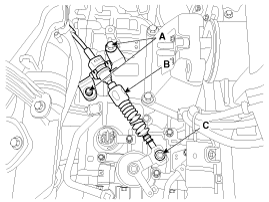
Remove the control cable (B) after removing the nut (C) and the bolt (A).
|
| 5. |
Remove the wiring bracket installation bolt (A, B).
|
| 6. |
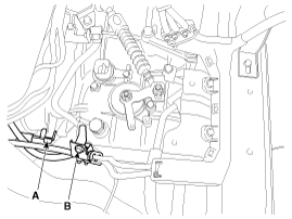
Disconnect the hose (B) after removing the automatic transaxle fluid cooler hose clamp (A).
|
| 7. |
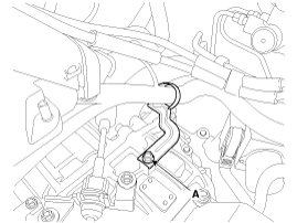
Remove the wiring bracket installation bolt (A).
|
| 8. |
Remove the ground line after removing the bolt (A).
|
| 9. |
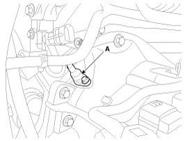
Remove the Crankshaft Position Sensor (A).
|
| 10. |
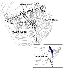
Install the towing eye (A).
|
| 11. |
Assemble the engine support fixture.
(Refer to Special Service Tools - "Engine support fixture assembly drawing") |
| 12. |
Install the engine support fixture.
|
| 13. |
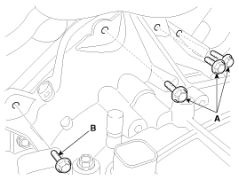
Remove the automatic transaxle upper mounting bolts (A, B).
|
| 14. |
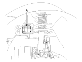
Remove the cover (A).
|
| 15. |
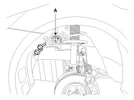
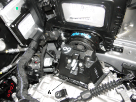
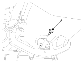
Remove the automatic transaxle mounting bracket bolt (A).
|
| 16. |
Remove the automatic transaxle support bracket (A).
|
| 17. |
Lift the vehicle with a jack. |
| 18. |
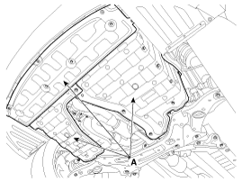
Remove the under cover (A).
|
| 19. |
Remove the drive shaft assembly.
(Refer to Driveshaft and axle - "Front Driveshaft") |
| 20. |
Remove the sub frame assembly.
(Refer to Suspension System - "Sub Frame") |
| 21. |
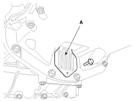
Remove the bell housing cover (A).
|
| 22. |
Remove the torque converter mounting bolt (A-6ea) with rotating the crankshaft.
|
| 23. |
Remove the starter mounting bolt (A).
|
| 24. |
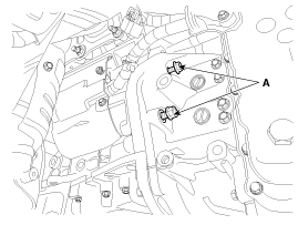
Remove the automatic transaxle with a jack after removing the mounting bolt (A-1ea, B-4ea).
|
| Installation |
| 1. |
Install in the reverse order of removal.
|
 Automatic Transaxle Components and Components Location
Components
1. Converter housing2. Automatic transaxle case3. Rear cover4. Valve body cover5. Manual control lever6. Air breather hose7. Inhibitor switch8. Solenoid valve connector
...
 Hydraulic System
...
Other information:
Kia Cadenza YG 2016-2025 Service Manual: ETC (Electronic Throttle Control) System Specifications
Specification [Throttle Position Sensor (TPS)] Throttle angle(°)Output Voltage (V) [Ref=5V]TPS1TPS200.54.5100.964.05201.413.59301.873.14402.322.68502.782.23603.231.77703.691.32804.140.86904.60.41984.650.35C.T (0)0.54.5W.O.T (86)4.410.59 [ETC Motor] ItemSpecificationCoil Resistance (Ω) ...
Kia Cadenza YG 2016-2025 Service Manual: Overdrive Clutch Control Solenoid Valve(OD/C_VFS) Specifications
Specification Item SpecificationControl typeN/H (Normal High)Control pressure kpa (kgf/cm², psi)"500.14 ~ 9.81 (5.1 ~ 0.1, 72.54 ~ 1.42)"Current value (mA)50 ~ 850Coil resistance(Ω)5.1 ± 0.3 ...
Copyright © www.kcadenzavg.com 2017-2025


