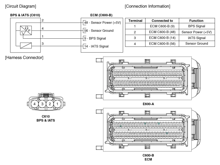
Kia Cadenza YG: Engine Control System / Barometric Pressure Sensor (BPS) Schematic Diagrams
| Circuit Diagram |
Specification Pressure [kPa (kgf/cm², psi)]Output Voltage (V)10.0 (0.01, 0.15)0.5055.0 (0.56, 7.98)2.21115.0 (1.17, 16.9)4.50
Inspection 1. Connect the GDS on the Data Link Connector (DLC). 2. Measure the output voltage of the BPS at idle and IG ON. Specification: Refer to "Specification" Removal 1.
Other information:
Kia Cadenza YG 2016-2021 Service Manual: Immobilizer Control Unit Repair procedures
Removal 1. Disconnect the negative (-) battery terminal. 2. Remove the crash pad lower panel. (Refer to Body - "Crash Pad") 3. Disconnect the 5P connector of the SMARTRA unit and then remove the SMARTRA unit (A) after loosening the bolt. Installation 1.
Kia Cadenza YG 2016-2021 Service Manual: Auto defoging sensor Repair procedures
Inspection 1. Press the OFF switch more then 4 times within 2 seconds while pressing the MODE switch. DisplayFail description00Normal23Auto defog sensor OPEN24Auto defog sensor SHORT43Defog door potentiometer OPEN/SHORT44Defog door potentiometer * Diagnostic procedure refer to DTC code.
Categories
- Manuals Home
- Kia Cadenza Owners Manual
- Kia Cadenza Service Manual
- Battery Troubleshooting
- Emission Control System
- Transaxle Control Module (TCM) Repair procedures
- New on site
- Most important about car
