Kia Cadenza YG: Cylinder Head Assembly / Components and Components Location
| Components |
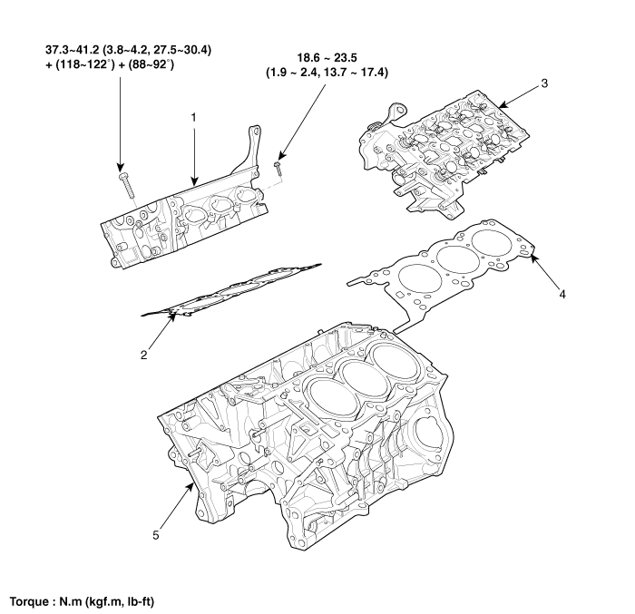
| 1. RH Cylinder head 2. RH Cylinder head gasket 3. LH Cylinder head | 4. LH Cylinder head gasket 5. Cylinder block |

| 1. Camshaft bearing cap 2. Camshaft thrust bearing cap 3. RH Exhaust camshaft 4. RH Intake camshaft 5. RH Exhaust CVVT assembly 6. RH Intake CVVT assembly 7. Mechanical lash adjuster (MLA) 8. Retainer lock | 9. Retainer 10. Valve spring 11. Valve stem seal 12. Valve 13. RH Intake camshaft OCV 14. RH Exhaust camshaft OCV 15. RH Cylinder head 16. LH Exhaust camshaft OCV | 17. LH Intake camshaft OCV 18. Fuel pump bracket 19. LH Intake camshaft 20. LH Exhaust camshaft 21. LH Intake CVVT assembly 22. LH Intake CVVT assembly 23. LH Cylinder head |
Valve Clearance Inspection And Adjustment Inspect and adjust the valve clearance when the engine is cold (Engine coolant temperature : 20°C(68°F)) and cylinder head is installed on the cylinder block.
Other information:
Kia Cadenza YG 2016-2021 Service Manual: Schematic Diagrams
Circuit Diagram SVM System Input/Output 1. Camera input ItemSpecificationLens angle of view190 degreesAngle of viewHorizontal186 degreesVertical135 degreesFunctionProvides the original image of the wide angle image (no additional function)Application locationSame camera applied to the front, rear, left and right 2.
Kia Cadenza YG 2016-2021 Service Manual: Description and Operation
Description System Overview The System offers the following features: – Human / machine interface through a 1-stage button, for terminal switching and engine start. – Control of external relays for ACC / IGN1 / IGN2 terminal switching and STARTER, without use of mechanical ignition switch.
Categories
- Manuals Home
- Kia Cadenza Owners Manual
- Kia Cadenza Service Manual
- Engine Mechanical System
- Rail Pressure Sensor (RPS) Schematic Diagrams
- Body Electrical System
- New on site
- Most important about car
