Kia Cadenza YG: Back View Camera System / Components and Components Location
Kia Cadenza YG 2016-2021 Service Manual / Body Electrical System / Back View Camera System / Components and Components Location
| Component Location |
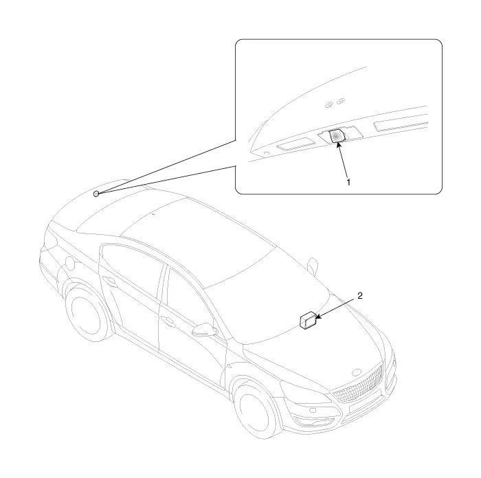
| 1. Back view camera | 2. AVN head unit |
Circuit Diagram
Other information:
Kia Cadenza YG 2016-2021 Service Manual: Description and Operation
Description The immobilizer system will disable the vehicle unless the proper ignition key is used, in addition to the currently available anti-theft systems such as car alarms, the immobilizer system aims to drastically reduce the rate of auto theft.
Kia Cadenza YG 2016-2021 Service Manual: Temperature Control Actuator Repair procedures
Inspection 1. Ignition "OFF" 2. Disconnect the connector of temperature control actuator. 3. Verify that the temperature control actuator operates to the hot position when connecting 12V to the terminal 3 and grounding terminal 7. Verify that the temperature control actuator operates to the cool position when connecting in the rev
Categories
- Manuals Home
- Kia Cadenza Owners Manual
- Kia Cadenza Service Manual
- General Information
- Automatic Transaxle System
- Engine Control / Fuel System
- New on site
- Most important about car

Copyright © 2026 www.kcadenzavg.com - 0.0344