Kia Cadenza YG: Air Conditioning System / Compressor Components and Components Location
Kia Cadenza YG 2016-2021 Service Manual / Heating,Ventilation, Air Conditioning / Air Conditioning System / Compressor Components and Components Location
| Components |
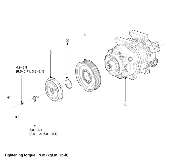
| 1. Screw 2. Blot 3. Limiter Assembly | 4. Retainer Ring 5. Pulley 6. Compressor Assembly |
Replacement 1. Discharge refrigerant from refrigeration system. 2. Replace faulty tube or hose. Cap the open fittings immediately to keep moisture or dirt out of the system.
Removal 1. If the compressor is marginally operable, run the engine at idle speed, and let the air conditioning work for a few minutes, then shut the engine off.
Other information:
Kia Cadenza YG 2016-2021 Service Manual: Start/Stop Button Repair procedures
Removal 1. Disconnect the negative (-) battery terminal. 2. Using a screw driver or remover, remove the center fascia lower panel (A). 3. Remove the in-car hose (A) and disconnect the connectors (B) from the heater & A/C control unit. 4.
Kia Cadenza YG 2016-2021 Service Manual: Components and Components Location
C
Categories
- Manuals Home
- Kia Cadenza Owners Manual
- Kia Cadenza Service Manual
- Automatic Transaxle System
- Transaxle Control Module (TCM) Repair procedures
- Engine Electrical System
- New on site
- Most important about car

Copyright © 2026 www.kcadenzavg.com - 0.0215