
Kia Cadenza YG: Engine Control System / Fuel Tank Pressure Sensor (FTPS) Schematic Diagrams
| Circuit Diagram |
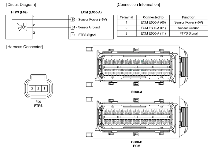
Specification Pressure [kPa (kgf/cm², psi)]Output Voltage (V)-6.67 (-0.06, -0.97)0.502.5+6.67 (0.068, 0.97)4.5
Inspection 1. Connect the GDS on the Data Link Connector (DLC). 2. Measure the output voltage of the FTPS. Specification: Refer to "Specification" Removal 1.
Other information:
Kia Cadenza YG 2016-2021 Service Manual: Blind Spot Detection Variant Coding Description and Operation
Description The used radar frequency of BSD is two, "North America region" and "Except North America region". If it replaces BSD unit, BSD unit has to perform the procedure of variant coding. BSD Variant Coding 1. Select the "BSD Variant Coding" procedure in BSD system.
Kia Cadenza YG 2016-2021 Service Manual: Specifications
Specification Air Conditioner ItemSpecificationCompressorType6VSX16Oil type & CapacityPAG OIL 100±10Pulley type6PK-TYPEDisplacement160cc/revCondenserHeat rejection14,400 ±5% kcal/hrA/C Pressure transducerThe method to measure the pressureVoltage= 0.
Categories
- Manuals Home
- Kia Cadenza Owners Manual
- Kia Cadenza Service Manual
- Body (Interior and Exterior)
- Emission Control System
- Battery Troubleshooting
- New on site
- Most important about car
