Kia Cadenza: Air Conditioning System / General Safety Information and Caution
Kia Cadenza YG 2016-2025 Service Manual / Heating,Ventilation, Air Conditioning / Air Conditioning System / General Safety Information and Caution
| Instructions |
When Handling Refrigerant
| 1. |
R-134a liquid refrigerant is highly volatile. A drop on the
skin of your hand could result in localized frostbite. When handling the
refrigerant, be sure to wear gloves. |
| 2. |
It is standard practice to wear goggles or glasses to protect
your eyes, and gloves to protect your hands. If the refrigerant
splashes into your eyes, wash them with clean water immediately. |
| 3. |
The R-134a container is highly pressurized. Never leave it in
a hot place, and check storage temperature is below 52°C (126°F). |
| 4. |
An electronic leak detector should be used to check the
system for refrigerant leakage. Bear in mind that the R-134a, upon
coming into contact with flame, produces phosgene, a highly toxic gas. |
| 5. |
Use only recommended lubricant for R-134a systems. If lubricants other than the recommended one used, system failure may occur. |
| 6. |
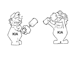
PAG lubricant absorbs moisture from the atmosphere at a rapid rate, therefore the following precautions must be observed:
|
| 7. |
If an accidental discharge in the system occurs, ventilate the work area before resum of service.
|
When replacing parts ON A/C system
| 1. |
Never open or loosen a connection before discharging the system. |
| 2. |
Seal the open fittings of components with a cap or plug immediately to prevent intrusion of moisture or dust. |
| 3. |
Do not remove the sealing caps from a Replacement component until it is ready to be installed. |
| 4. |
Before connecting an open fitting, always install a new
sealing ring. Coat the fitting and seal with refrigerant oil before
making the connection.
|
When Installing Connecting Parts
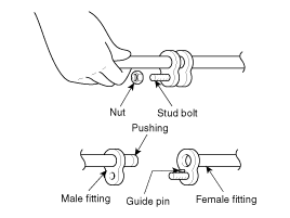
Flange With Guide Pin
Check the new O-ring for damage (use only the specified) and
lubricate it using compressor oil. Tighten the nut to specified torque.

| Size | Tightening torque N.m (Kgf.m, Ib-ft)) | |
| Bolt, Nut | ||
| Bolt(4T), Nut(4T) | Bolt(8T), Nut(6T) | |
| M6 | 3.9-5.8(0.4 - 0.6,2.8-4.3) | 7.8-11.7(0.8 - 1.2,5.7-8.6) |
| M8 | 8.8-13.7(0.9 - 1.4,6.5-10.1) | 19.6-29.4(2.0 - 3.0,14.4-21.6) |
| M10 | 18.6-27.4(1.9 – 2.8,13.7-20.2) | 44.1-58.8(4.5 - 6.0,32.5-43.3) |
| Size | Flange Bolt, Nut | |
| Bolt(4T), Nut(4T) | Bolt(8T), Nut(6T) | |
| M6 | 3.9-5.8(0.4 - 0.6,2.8-4.3) | 8.8-13.7(0.9 - 1.4,6.5-10.1) |
| M8 | 9.8-14.7(1.0 - 1.5,7.2-10.8) | 21.5-32.3(2.2 - 3.3,15.9-23.8) |
| M10 | 20.5-30.4(2.1 - 3.1,15.1-22.4) | 49.0-63.7(5.0 - 6.5,36.1-47.0) |
|
Handling tubing and fittings
The internal parts of the refrigeration system will remain in
a state of chemical stability as long as pure moisture-free refrigerant
and refrigerant oil are used. Abnormal amounts of dirt, moisture or air
can upset the chemical stability and cause problems or serious damage.
The Following precautions must be observed
| 1. |
When it is necessary to open the refrigeration system, have
everything you will need to service the system ready so the system will
not be left open any longer than necessary. |
| 2. |
Cap or plug all lines and fittings as soon as they are opened to prevent the entrance of dirt and moisture. |
| 3. |
All lines and components in parts stock should be capped or sealed until they are ready to be used. |
| 4. |
Never attempt to rebind formed lines to fit. Use the correct line for the installation you are servicing. |
| 5. |
All tools, including the refrigerant dispensing manifold, the gauge set manifold and test hoses, should be kept clean and dry. |
 Description and Operation
Refrigeration Cycle
...
Other information:
Kia Cadenza YG 2016-2025 Owners Manual: Shift lock system
For your safety, the automatic transmission has a shift lock system which prevents shifting the transmission from P (Park) into R (Reverse) unless the brake pedal is depressed. To shift the transmission from P (Park) into R (Reverse): 1.Depress and hold the brake pedal. 2.Start the engi ...
Kia Cadenza YG 2016-2025 Service Manual: Components and Components Location
Component Location 1. Auto light sensor2. Head lamps3. Lighting switch (Auto)4. Tail lamps5. IPM (Intelligent intergrated Platform Module) ...
Copyright © www.kcadenzavg.com 2017-2025


