Kia Cadenza: Blower / Power Mosfet Repair procedures
Kia Cadenza YG 2016-2025 Service Manual / Heating,Ventilation, Air Conditioning / Blower / Power Mosfet Repair procedures
| Inspection |
| 1. |
Ignition "ON" |
| 2. |
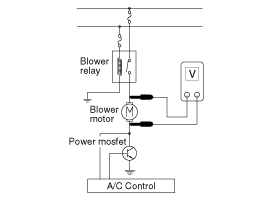
Manually operate the control switch and measure the voltage of blower motor. |
| 3. |
Select the control switch to raise voltage until high speed.
Specification
*AUTO COOLING: Auto speed (4.5V~B+)
*AUTO HEATING: Auto speed (4.5V~11.0V) |
| 4. |
If the measured voltage is not specification, substitute with a known-good power mosfet and check for proper operation. |
| 5. |
If the problem is corrected, replace the power mosfet. |
| Replacement |
| 1. |
Disconnect the negative (-) battery terminal. |
| 2. |
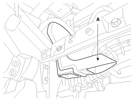
Remove the crash pad lower cover (A) and then disconnect the connector (B).
|
| 3. |
Remove the shower duct(A).
|
| 4. |
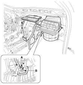
Disconnect the power mosfet connector (A) and then remove the power mosfet (B) after loosening the mounting screws.
|
| 5. |
Installation is the reverse order of removal. |
 Blower Motor Repair procedures
Inspection
1.
Connect the battery voltage and check the blower motor rotation.
2.
If the blower motor voltage is not operated well, substitute with a known-good blower motor and check for prop ...
 Blower Resistor Repair procedures
Inspection
1.
Measure terminal - to - terminal resistance of blower resistor.
2.
If measure resistance isnot within specification, the blower resistor must be replaced.
Replacement
1.
Dis ...
Other information:
Kia Cadenza YG 2016-2025 Owners Manual: Front windshield washers
In the OFF position, pull the lever gently toward you to spray washer fluid on the windshield and to run the wipers 1-3 cycles. Use this function when the windshield is dirty. The spray and wiper operation will continue until you release the lever. If the washer does not work, check ...
Kia Cadenza YG 2016-2025 Owners Manual: Automatic climate control system
■ Type A ■ Type B System Overview 1. Front windshield defroster button 2. Rear window defroster button 3. SYNC temperature control selection button 4. Passenger's temperature control button 5. Driver’s temperature control button 6. AUTO (automatic control) button 7. OFF butt ...
Copyright © www.kcadenzavg.com 2017-2025


