Kia Cadenza YG: Emission Control System / Schematic Diagrams
| Schematic Diagram |
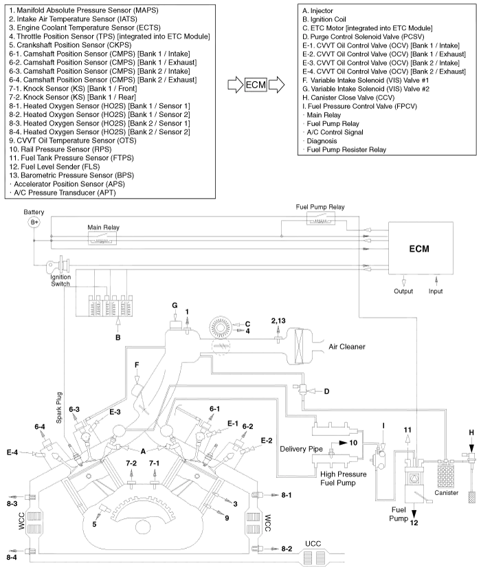
Description Emissions Control System consists of three major systems. • Crankcase Emission Control System prevents blow-by gas from releasing into the atmosphere.
Troubleshooting SymptomSuspect areaEngine will not start or stuggle to startVapor hose damaged or disconnectedEngine stuggle to startMalfunction of the Purge Control Solenoid ValveRough idle or engine stallsVapor hose damaged or disconnectedMalfunction of the PCV valveRough idleMalfunction of the Evaporative Emission Control SystemExcessive oil consumptionPositive crankcase ventilation line clogged
Other information:
Kia Cadenza YG 2016-2021 Service Manual: Schematic Diagrams
C
Kia Cadenza YG 2016-2021 Service Manual: Evaporator unit Repair procedures
Inspection 1. Ignition "OFF". 2. Disconnect evaporator temperature sensor. 3. Using the multi-tester, Measure resistance between terminal "1" and "2" of evaporator temperature sensor. Specification Evaporator coretemperature [°C(°F)]Resistance[KΩ]Voltage[V]-20(-4)70.
Categories
- Manuals Home
- Kia Cadenza Owners Manual
- Kia Cadenza Service Manual
- Specifications
- Rail Pressure Sensor (RPS) Schematic Diagrams
- Transaxle Control Module (TCM) Repair procedures
- New on site
- Most important about car
