Kia Cadenza YG: Electric Power Steering / Schematic Diagrams
Kia Cadenza YG 2016-2021 Service Manual / Steering System / Electric Power Steering / Schematic Diagrams
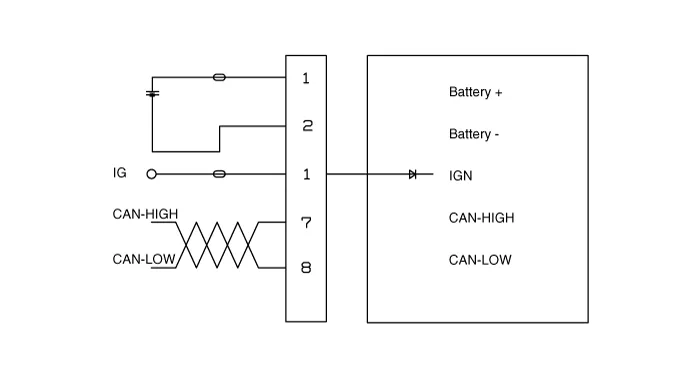
| MDPS Circuit Diagram |
Harness Connector
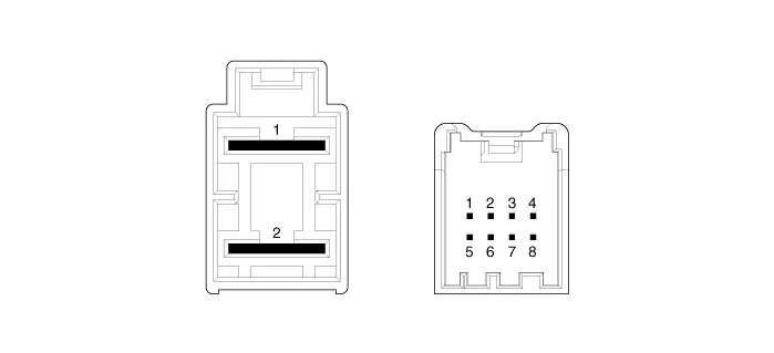
| Type | Pin No | Description |
| Battery | 1 | Battery + |
| 2 | Battery - | |
| Vehicle | 1 | IGN |
| 2 | - | |
| 3 | - | |
| 4 | - | |
| 5 | - | |
| 6 | - | |
| 7 | High_CAN | |
| 8 | Low_CAN |
Components 1. Steering column2. ECU3. Motor4. Steering gear box
General Inspection After or before servicing the EPS system, perform the troubleshooting and test procedure as follows. Compare the system condition with normal condition in the table below and if abnormal symptom is detected, perform necessary remedy and inspection.
Categories
- Manuals Home
- Kia Cadenza Owners Manual
- Kia Cadenza Service Manual
- Alternator Schematic Diagrams
- Emission Control System
- Suspension System
- New on site
- Most important about car

Copyright © 2026 www.kcadenzavg.com - 0.0252