Kia Cadenza YG: Smart Cruise Control System / Smart Cruise Control Unit Schematic Diagrams
| Circuit Diagram |
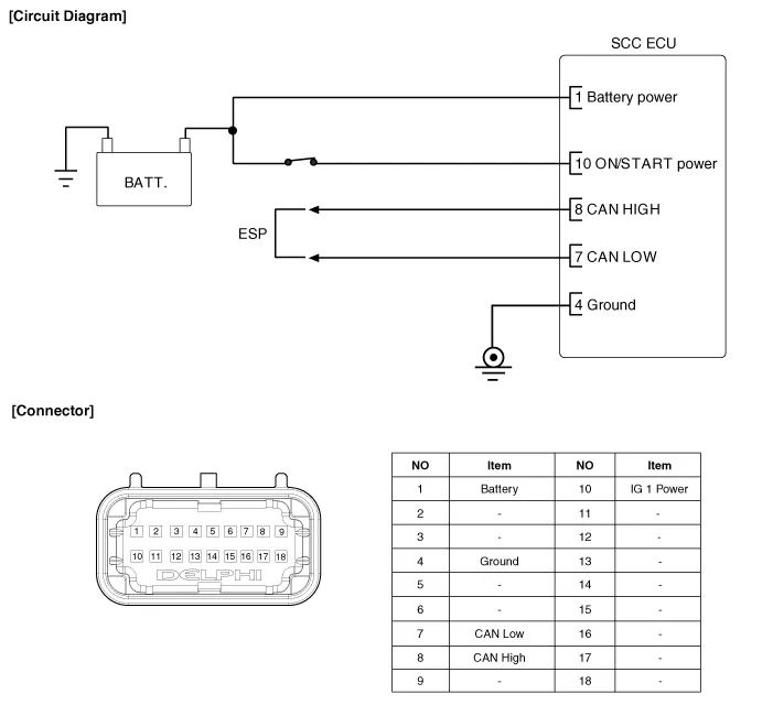
Specification ItemSpecificationPower supply(V)12Operation voltage (V)9 ~ 16
Removal 1. Turn the ignition switch OFF and disconnect the battery negative (-) cable. 2. Remove the front bumper. (Refer to Body - "Front Bumper") 3.
Other information:
Kia Cadenza YG 2016-2021 Service Manual: Components and Components Location
Component Location 1. Start Stop Button(SSB)2. FOB key3. RF receiver4. Smart key unit5. Interior antenna 16. Interior antenna 2 7. Trunk antenna8. Bumper antenna9. Door handle & door antenna10. Trunk lid open switch11.
Kia Cadenza YG 2016-2021 Service Manual: Mode Control Actuator Repair procedures
Inspection 1. Ignition "OFF” 2. Disconnect the connector of mode control actuator. 3. Verify that the mode control actuator operates to the defrost mode when connecting 12V to the terminal 3and grounding terminal 7. 4. Verify that the mode control actuator operates to the vent mode when connecting in the reverse.
Categories
- Manuals Home
- Kia Cadenza Owners Manual
- Kia Cadenza Service Manual
- Suspension System
- Specifications
- Steering System
- New on site
- Most important about car
