Kia Cadenza YG: Tire Pressure Monitoring System / TPMS Receiver Description and Operation
| Description |
| 1. |
Mode
|
| 2. |
Overview
|
Removal 1. Remove the tire. 2. Remove the foreign substance from wheel. 3. Discharge the air to the tire air inlet (A). 4. Install the bead brake from the tire and then remove the the tire rim by stepping slide bar, a pedal.
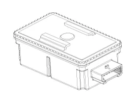
Circuit Diagram Connector pin number Pin No.Pinning1V_BAT_ECU2IG_ON3CAN_High4CAN_Low5GND6NA
Other information:
Kia Cadenza YG 2016-2021 Service Manual: Repair procedures
Inspection Initialization and diagnosis sequence by using diagnostic equipment Below content summarize the procedure for A/S using Diagnostic equipment Download Parameter 1. Select "AFLS" menu after selecting a vehicle. 2. Select "Parameter download" menu for define a characteristc of vehicle.
Kia Cadenza YG 2016-2021 Service Manual: Blower Unit Repair procedures
Replacement 1. Disconnect the negative (-) battery terminal. 2. Remove the heater and blower unit.(Refer to HA group – heater unit). 3. Remove the blower unit (A) from the heater unit after loosening a mounting bolt and 3 screws. Make sure that there is no air leaking out of the blower and duct joints.
Categories
- Manuals Home
- Kia Cadenza Owners Manual
- Kia Cadenza Service Manual
- Engine Mechanical System
- Timing Chain Repair procedures
- Body Electrical System
- New on site
- Most important about car
