Kia Cadenza YG: Clutch & Brake / Components and Components Location
| Components Location |
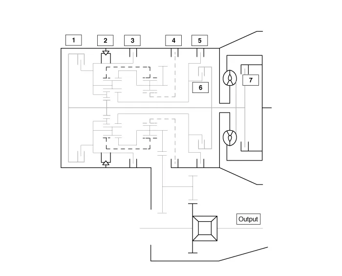
| 1. Overdrive clutch (OD/C) 2. One way clutch (OWC) 3. Low & Reverse brake (LR/B) 4. Underdrive brake (UD/B) | 5. 26 brake(26/B) 6. 35R clutch (35R/C) 7. Damper clutch (D/C) |
Description The 6-speed automatic transaxle consists of an overdrive clutch (OD/C), a one-way clutch (OWC), a lower and reverse brake (LR/B), an underdrive brake (UD/B), a 26 brake (26/B), and a 35R clutch (35R/C).
Power Flow Chart P,NUD/BLR/B26/B35R/COD/COWC● ▣ Direction of Rotation ▶Lower & Reverse Brake (LR/B) Activation → Overdrive (O/D) Hub Lock → Mid & Rear P/C Lock ▶Input Shaft Rotation → Rear Sun Gear Rotation → Rear Inner Pinion Rotation (Reverse) → Rear Outer Pinion Rotation → Rear Annulus Gear Rotation → Front Annulus Gear Rotation → Front Pinion Rotation → Front Sun Gear Rotation (Reverse) → Underdrive (U/D) Hub Rotation (Reverse) ▶Input shaft rotation → Overdrive Clutch (OD/C) Retainer Rotation ▶Input shaft rotation → 35R Clutch Rotation RUD/BLR/B26/B35R/COD/COWC●● ▣ Power Delivery Route ▶ Middle carrier locked and middle sun gear in rotation ▶ Rotating the middle planetary gear''s sun gear while its carrier is locked in place slows down and reverse rotates the annulus gear (front carrier), resulting in power transfer to the front carrier.
Other information:
Kia Cadenza YG 2016-2021 Service Manual: Compressor Oil Repair procedures
Oil Specification 1. The HFC-134a system requires synthetic (PAG) compressor oil whereas the R-12 system requires mineral compressor oil. The two oils must never be mixed. 2. Compressor (PAG) oil varies according to compressor model. Be sure to use oil specified for the model of compressor.
Kia Cadenza YG 2016-2021 Service Manual: Condenser Repair procedures
Inspection 1. Check the condenser fins for clogging and damage. If clogged, clean them with water, and blow them with compressed air. If bent, gently bend them using a screwdriver or pliers. 2. Check the condenser connections for leakage, and repair or replace it, if required.
Categories
- Manuals Home
- Kia Cadenza Owners Manual
- Kia Cadenza Service Manual
- Body Electrical System
- Transaxle Control Module (TCM) Repair procedures
- Rail Pressure Sensor (RPS) Schematic Diagrams
- New on site
- Most important about car
