Kia Cadenza YG: Timing System / Crankshaft Damper Pulley Components and Components Location
| Components |
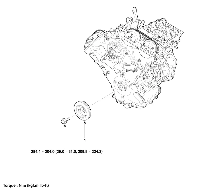
| 1. Crankshaft damper pulley |
Removal and Installation 1. Remove the drive belt idler. (Refer to Timing System - "Idler") 2. Remove the drive belt auto tensioner (A). Tightening torque Bolt (B) : 81.
Removal and Installation • Use fender covers to avoid damaging painted surfaces. • To avoid damage, unplug the wiring connectors carefully while holding the connector portion.
Other information:
Kia Cadenza YG 2016-2021 Service Manual: Start/Stop Button Repair procedures
Removal 1. Disconnect the negative (-) battery terminal. 2. Using a screw driver or remover, remove the center fascia lower panel (A). 3. Remove the in-car hose (A) and disconnect the connectors (B) from the heater & A/C control unit. 4.
Kia Cadenza YG 2016-2021 Service Manual: Repair procedures
Refrigerant System Service Basics Refrigerant Recovery Use only service equipment that is U.L-listed and is certified to meet the requirements of SAE J2210 to remove HFC-134a(R-134a) from the air conditioning system. – Air conditioning refrigerant or lubricant vapor can irritate your eyes, nose, or th
Categories
- Manuals Home
- Kia Cadenza Owners Manual
- Kia Cadenza Service Manual
- Body Electrical System
- Engine Mechanical System
- Engine Electrical System
- New on site
- Most important about car
