Kia Cadenza YG: Parking Brake System / Electric Parking Brake (EPB) Schematic Diagrams
| EPB Circuit Diagram |
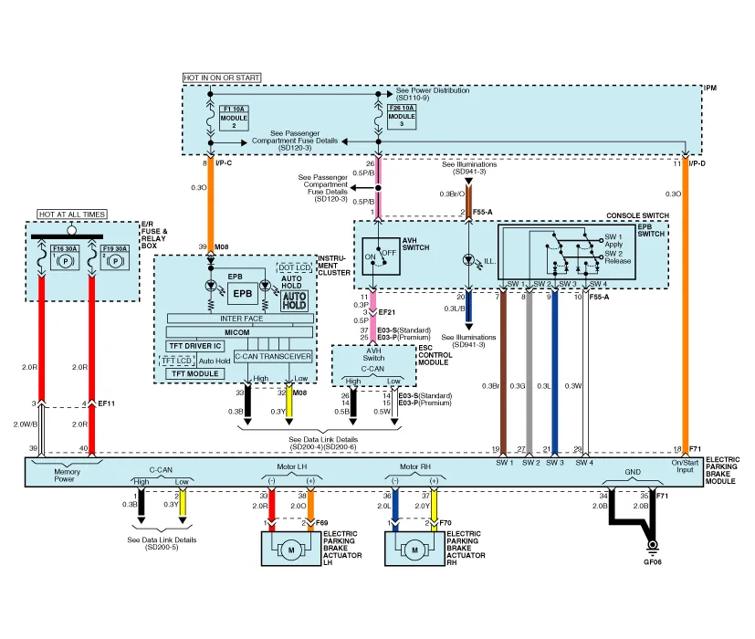
| EPB connector input/output |

| Pin No. | Description |
| 1 | CAN_High |
| 2 | CAN_Low |
| 18 | IGN (+) |
| 19 | EPB Switch Signal 1 |
| 21 | EPB Switch Signal 3 |
| 27 | EPB Switch Signal 2 |
| 29 | EPB Switch Signal 4 |
| 33 | Rear Left Motor (-) |
| 34 | Ground |
| 35 | Ground |
| 36 | Rear Right Motor (-) |
| 37 | Rear Right Motor (+) |
| 38 | Rear Left Motor (+) |
| 39 | Battery (Rear Right Motor) |
| 40 | Battery (Rear Left Motor) |
Description The EPB is an electronic parking brake. The EPB is different from existing parking systems which operated with the brake pedal or the lever type.
Removal 1. Turn ignition OFF and disconnect the negative (-) battery cable. 2. Remove the crash pad lower panel and reinforcing panel (A). (Refer to the Body group - “Crash pad”) 3.
Other information:
Kia Cadenza YG 2016-2021 Service Manual: Repair procedures
Inspection Tolerance Calibration Tolerance calibration compensates for the error margins of surround view video that occur due to the installation tolerance when the four cameras that comprise the SVM system are installed. You must carry out tolerance calibration if you do any of the following.
Kia Cadenza YG 2016-2021 Service Manual: Temperature Control Actuator Repair procedures
Inspection 1. Ignition "OFF" 2. Disconnect the connector of temperature control actuator. 3. Verify that the temperature control actuator operates to the hot position when connecting 12V to the terminal 3 and grounding terminal 7. Verify that the temperature control actuator operates to the cool position when connecting in the rev
Categories
- Manuals Home
- Kia Cadenza Owners Manual
- Kia Cadenza Service Manual
- Steering System
- Alternator Schematic Diagrams
- Automatic Transaxle System
- New on site
- Most important about car
