Kia Cadenza: Fuel Delivery System / Fuel Pump Control Module (FPCM) Repair procedures
Kia Cadenza YG 2016-2025 Service Manual / Engine Control / Fuel System / Fuel Delivery System / Fuel Pump Control Module (FPCM) Repair procedures
| Removal |
| 1. |
Turn the ignition switch OFF and disconnect the battery negative (-) cable. |
| 2. |
Lift the vehicle. |
| 3. |
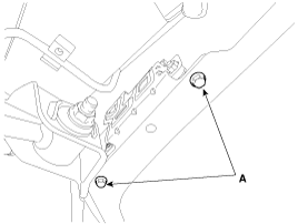
Remove the fuel pump control module mounting bolts (A).
|
| 4. |
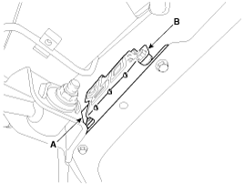
Disconnect the fuel pump control module connector (A), and then remove the module (B) from the vehicle.
|
| Installation |
| 1. |
Install in the reverse order of removal. |
| Inspection |
| 1. |
Connect the GDS to the vehicle''s data link connector (DLC). |
| 2. |
Check any DTCs and if exist, repair according to the DTC guide. |
| 3. |
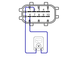
Check the power supply voltage provided to the fuel pressure sensor (FPS).
|
| 4. |
Check the voltage provided to the fuel pressure sensor (FPS) at idle.
|
| 5. |
Check the fuel pressure in the low fuel line.
(Refer to Fuel Delivery System - "Fuel Pressure Test")
|
 Fuel Pump Control Module (FPCM) Schematic Diagrams
Circuit Diagram
Fuel Pressure Control Module (FPCM) Terminal And Input/Output signal
FPCM Terminal Function
Pin No.DescriptionConnected to1Fuel pressure sensor (FPS) power supply (+5V)Fuel Pres ...
 Fuel Pressure Sensor (FPS) Description and Operation
Description
The fuel pressure sensor (FPS) is installed on the top of the
low pressure fuel pump and measures the pressure in the low pressure
fuel line.
Based on the fuel pressure measured by ...
Other information:
Kia Cadenza YG 2016-2025 Service Manual: Components and Components Location
Components Location [Fuel Tank] 1. Fuel Tank2. Fuel Pump3. Fuel Filter4. Fuel Pressure Regulator5. Canister6. Fuel Tank Air Filter7. Fuel Pressure Sensor (FPS)8. Fuel Tank Pressure Sensor (FTPS)9. Canister Close Valve (CCV)10. Fuel Level Sender (FLS)11. Fuel Pump Control Module (FPCM)1 ...
Kia Cadenza YG 2016-2025 Service Manual: Antenna Repair procedures
Inspection Glass Antenna Test 1. Wrap aluminum foil (A) around the tip of the tester probe (B) as shown. 2. Touch one tester probe to the glass antenna terminal (A) and move the other tester probe along the antenna wires to check that continuity exists. Glass Antenna Repair ...
Copyright © www.kcadenzavg.com 2017-2025


