Kia Cadenza YG: Fuel Delivery System / Fuel Pump Control Module (FPCM) Schematic Diagrams
Kia Cadenza YG 2016-2021 Service Manual / Engine Control / Fuel System / Fuel Delivery System / Fuel Pump Control Module (FPCM) Schematic Diagrams
| Circuit Diagram |
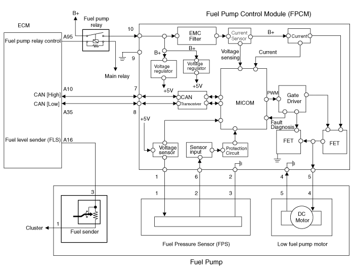
| Fuel Pressure Control Module (FPCM) Terminal And Input/Output signal |

FPCM Terminal Function
| Pin No. | Description | Connected to |
| 1 | Fuel pressure sensor (FPS) power supply (+5V) | Fuel Pressure Sensor (FPS) |
| 2 | Fuel Pressure Sensor (FPS) Ground (-) | Fuel Pressure Sensor (FPS) |
| 3 | - | |
| 4 | Fuel pump DC motor (-) | Fuel Pump Motor |
| 5 | Fuel pump DC motor (+) | Fuel Pump Motor |
| 6 | Fuel pressure sensor (FPS) signal input | Fuel pressure sensor (FPS) |
| 7 | CAN [High] | ECM |
| 8 | CAN [Low] | ECM |
| 9 | Ground | Chassis Ground |
| 10 | Battery power (B+) | Fuel Pump Relay |
Specification ItemsSpecificationApplied Voltate (V)6~18Current Consumption (A)Max. 15Fuel Pressure StartMax. 600 KPa (Max. 6.1 kgf/cm², Max.
Removal 1. Turn the ignition switch OFF and disconnect the battery negative (-) cable. 2. Lift the vehicle. 3. Remove the fuel pump control module mounting bolts (A).
Other information:
Kia Cadenza YG 2016-2021 Service Manual: Components and Components Location
C
Kia Cadenza YG 2016-2021 Service Manual: Blower Resistor Repair procedures
Inspection 1. Measure terminal - to - terminal resistance of blower resistor. 2. If measure resistance isnot within specification, the blower resistor must be replaced. Replacement 1. Disconnect the negative (-) battery terminal. 2. Remove the crash pad lower cover (A) and then disconnect the connector (B).
Categories
- Manuals Home
- Kia Cadenza Owners Manual
- Kia Cadenza Service Manual
- Battery Troubleshooting
- Transaxle Control Module (TCM) Repair procedures
- Timing Chain Repair procedures
- New on site
- Most important about car

Copyright © 2026 www.kcadenzavg.com - 0.0406