Kia Cadenza YG: Hydraulic System / Oil Pump Description and Operation
Kia Cadenza YG 2016-2021 Service Manual / Automatic Transaxle System / Hydraulic System / Oil Pump Description and Operation
| Description |
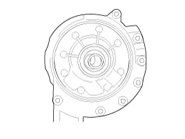
The oil pump is built-in as a single unit with the 26 Brake
chamber. Rotation of the pump builds the hydraulic pressure needed for
the lubrication of the various parts of the transaxle and operation of
the clutch and brakes. The oil also circulates through the torque
converter and the cooler.
Components Location 1. Automatic transaxle2. Valve body assembly3. Oil pump assembly
Components 1. Reaction shaft support assembly2. Oil pump housing3. Driven gear4. Drive gear5. Oil seal6. Bush-Housing7. Reaction shaft8. Bush- Reaction shaft9.
Categories
- Manuals Home
- Kia Cadenza Owners Manual
- Kia Cadenza Service Manual
- Specifications
- Restraint
- General Information
- New on site
- Most important about car

Copyright © 2026 www.kcadenzavg.com - 0.0214