Kia Cadenza: Seat Electrical / Power Seat Control Switch Repair procedures
Kia Cadenza YG 2016-2025 Service Manual / Body Electrical System / Seat Electrical / Power Seat Control Switch Repair procedures
| Inspection |
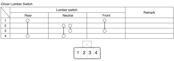
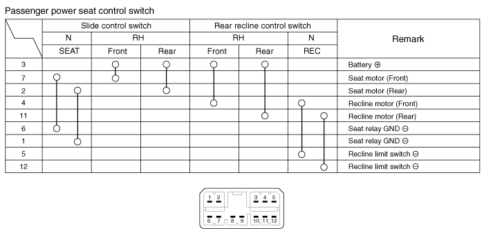
With the power seat switch in each position, make sure that
continuity exists between the terminals below. If continuity is not as
specified, replace the power seat switch.
A : Power seat control switch
B : Lumber support switch
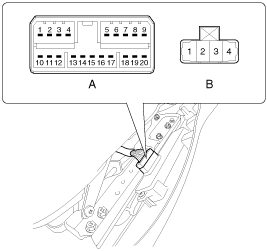

In case of IMS switch inspection, refer to "IMS" system. |
| Removal |
| 1. |
Disconnect the negative (-) battery terminal. |
| 2. |
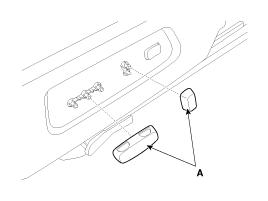
Remove the switchs (A) from seat side cover.
|
| 3. |
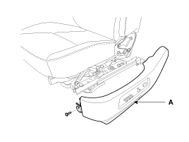
Remove the seat side cover (A).
(Refer to Body - "Front Seat")
|
| 4. |
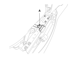
Disconnect the power seat control switch connector (A).
|
| 5. |
Loosen the power seat control switch (A) mounting screws (3EA).
|
| Installation |
|
| 1. |
Connect the connectors and reassemble the IMS control switch. |
| 2. |
Reassemble the seat side cover. |
 Power Seat Control Switch Schematic Diagrams
Circuit Diagram
...
 Seat Heater Components and Components Location
Component Location
...
Other information:
Kia Cadenza YG 2016-2025 Service Manual: CVVT & Camshaft Components and Components Location
Components 1. RH exhaust camshaft2. RH intake camshaft3. LH intake camshaft4. LH exhaust camshaft 1. RH exhaust CVVT2. RH intake CVVT3. LH intake CVVT4. LH exhaust CVVT ...
Kia Cadenza YG 2016-2025 Owners Manual: System setting
The driver can change LKA to Lane Departure Warning (LDW) or change the LKA mode Selecting “Settings > Vehicle > Driver Assistance > Lane Safety > Lane Keeping Assist/Lane Departure Warning/Off” in the Infotainment System screen. Lane Keeping Assist LKA mode guides the ...
Copyright © www.kcadenzavg.com 2017-2025


