Kia Cadenza YG: Fuses And Relays / Relay Box (Engine Compartment) Repair procedures
Kia Cadenza YG 2016-2021 Service Manual / Body Electrical System / Fuses And Relays / Relay Box (Engine Compartment) Repair procedures
| Inspection |
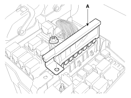
Power Relay Test (Type A)
|

Check for continuity between the terminals.
| A. Front deicer B. IGN2 relay C. Blower relay D. Burglar alarm horn relay E. IGN1 relay F. Cooling fan #1 relay | G. Cooling fan #2 relay H. Start relay I. Rear defogger J. Horn relay K. ACC relay L. Fuel pump relay |
| 1. |
There should be continuity between the No.30 and No.87
terminals when power and ground are connected to the No.85 and No.86
terminals. |
| 2. |
There should be no continuity between the No.30 and No.87 terminals when power is disconnected.
|


Power Relay Test (Type B)
Check for continuity between the terminals.
A : Rain sensor relay
B : Wiper relay
| 1. |
There should be continuity between the No.30 and No.87
terminals when power and ground are connected to the No.85 and No.86
terminals. |
| 2. |
There should be continuity between the No.30 and No.87 terminals when power is disconnected.
|


Power Relay Test (Type C)
Check for continuity between the terminals.
A : ECU relay
| 1. |
There should be continuity between the No.30, 87a and No.87
terminals when power and ground are connected to the No.85 and No.86
terminals. |
| 2. |
There should be no continuity between the No.30, 87a and No.87 terminals when power is disconnected.
|


Fuse Inspection
| 1. |
Be sure there is no play in the fuse holders, and that the fuses are held securely. |
| 2. |
Are the fuse capacities for each circuit correct? |
| 3. |
Are there any blown fuses?
If a fuse is to be replaced, be sure to use a new fuse of the
same capacity. Always determine why the fuse blew first and completely
eliminate the problem before installing a new fuse. |
Multi Fuse
Multi Fuse is for optimizing the engine room package.
|
Other information:
Kia Cadenza YG 2016-2021 Service Manual: Surround View Monitoring Unit Repair procedures
Removal 1. Disconnect the negative (-) battery terminal. 2. Remove the glove box housing. (Refer to Body - "Glove Box Housing") 3. Remove the SVM unit (B) after disconnecting the connectors (A) and mounting bolts. Installation 1. Install the SVM unit.
Kia Cadenza YG 2016-2021 Service Manual: Mode Control Actuator Repair procedures
Inspection 1. Ignition "OFF” 2. Disconnect the connector of mode control actuator. 3. Verify that the mode control actuator operates to the defrost mode when connecting 12V to the terminal 3and grounding terminal 7. 4. Verify that the mode control actuator operates to the vent mode when connecting in the reverse.
Categories
- Manuals Home
- Kia Cadenza Owners Manual
- Kia Cadenza Service Manual
- Emission Control System
- Body (Interior and Exterior)
- Steering System
- New on site
- Most important about car

Copyright © 2026 www.kcadenzavg.com - 0.0239