Kia Cadenza YG: Crankcase Emission Control System / Schematic Diagrams
Kia Cadenza YG 2016-2021 Service Manual / Emission Control System / Crankcase Emission Control System / Schematic Diagrams
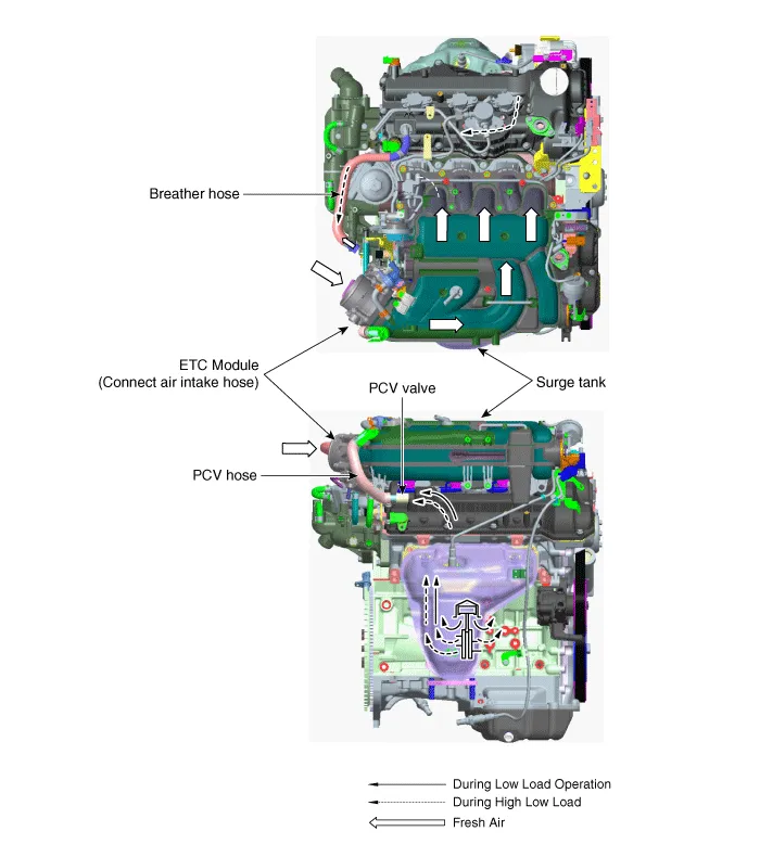
| Schematic Diagram |
Inspection 1. After disconnecting the vapor hose from the PCV valve, remove the PCV valve. 2. Reconnect the PCV valve to the vapor hose. 3.
Other information:
Kia Cadenza YG 2016-2021 Service Manual: Auto Head lamp leveling Unit Repair procedures
Removal Height Sensor 1. Remove the height sensor connector (A). 2. Loosen the mounting bolts(Body: 2EA, chassis: 1EA) from height sensor bracket. Tightening torque : 3 ~ 5N.m (30 ~ 50kgf.m, 2.21 ~ 3.68lb-ft) 3. Remove the height sensor.
Kia Cadenza YG 2016-2021 Service Manual: A/C Pressure Transducer Repair procedures
Inspection 1. Measure the pressure of high pressure line by measuring voltage output between NO.1 and NO.2 terminals. 2. Inspect the voltage value whether it is sufficient to be regular value or not. Voltage = 0.00878835 * Pressure + 0.37081095 [PSIA] 3.
Categories
- Manuals Home
- Kia Cadenza Owners Manual
- Kia Cadenza Service Manual
- Engine Electrical System
- General Information
- Engine Control / Fuel System
- New on site
- Most important about car

Copyright © 2026 www.kcadenzavg.com - 0.0205