Kia Cadenza: IMS (Integrated Memory) / Schematic Diagrams
Kia Cadenza YG 2016-2025 Service Manual / Body Electrical System / IMS (Integrated Memory) / Schematic Diagrams
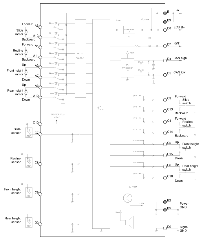
| Circuit Diagram |

| Input/Output Specification |
| Connector Pin Lay Out |

IMS input/output pin information
| No | Signal Name | I/O | Contents | Remark |
| A1 | - | - | - | |
| A2 | FR height motor up | O | FR height motor up output | |
| A3 | RR height motor up | O | RR height motor up output | |
| A4 | Recline motor FR | O | Recline motor FR output | |
| A5 | Slide motor FR | O | Slide motor FR output | |
| A6 | - | - | - | |
| A7 | FR height motor down | O | FR height motor down output | |
| A8 | - | - | - | |
| A9 | - | - | - | |
| A10 | RR height motor down | O | RR height motor down output | |
| A11 | Recline motor RR | O | Recline motor RR output | |
| A12 | Slide motor RR | O | Slide motor RR output | |
| B1 | GND(Power) | I | Power B+ for operating motor | |
| B2 | GND (Power) | I | Power GND for operating motor | |
| B3 | B+(Power) | I | Power B+ for operating motor | |
| B4 | - | - | - | |
| B5 | GND (Power) | I | Power GND for operating motor | |
| C1 | - | - | - | |
| C2 | - | - | - | |
| C3 | Slide FR manual switch | I | Slide FR manual switch input | On : GND |
| C4 | Recline FR manual switch | I | Recline FR manual switch input | On : GND |
| C5 | FR height up manual switch | I | FR height up manual switch input | On : GND |
| C6 | RR height up manual switch | I | RR height up manual switch input | On : GND |
| C7 | Slide motor sensor | I | Slide motor sensor input | Pulse signal |
| C8 | Recline motor sensor | I | Recline motor sensor input | Pulse signal |
| C9 | FR height motor sensor | I | FR height motor sensor input | Pulse signal |
| C10 | Sensor Vcc(Seat) | O | VCC for operating sensor | 5V |
| C11 | - | - | - | |
| C12 | - | - | - | |
| C13 | Slide RR manual switch | I | Slide RR manual switch input | ON : GND |
| C14 | Recline RR manual switch | I | Recline RR manual switch input | ON : GND |
| C15 | FR height down manual switch | I | FR height down manual switch input | ON : GND |
| C16 | RR height down manual switch | - | RR height down manual switch input | ON : GND |
| C17 | - | - | - | |
| C18 | - | - | - | |
| C19 | - | - | - | |
| C20 | - | - | - | |
| D1 | - | - | - | |
| D2 | RR height up sensor | I | RR height up motor sensor | Pulse signal |
| D3 | - | - | - | |
| D4 | CAN high | I/O | CAN | |
| D5 | CAN low | I/O | CAN | |
| D6 | - | - | - | |
| D7 | IGN1 | I | IGN1 input | BAT |
| D8 | B+(ECU) | I | ECU power input | BAT |
| D9 | GND(ECU) | I | ECU GND | |
| D10 | - | - | - | |
| D11 | - | - | - | |
| D12 | - | - | - | |
| D13 | - | - | - | |
| D14 | - | - | - | |
| D15 | - | - | - | |
| D16 | - | - | - |
| Communication System |

 Components and Components Location
Component Location
1. Seat Memory Unit (IMS)2. IMS control switch3. IMS driver power seat control
...
 Description and Operation
Description
system outline
An optimal seat position set by a driver can be memorized in
Power seat unit by IMS SW, which enables restoration of seat position
set by the driver despite
Playi ...
Other information:
Kia Cadenza YG 2016-2025 Service Manual: Water pump Components and Components Location
Components 1. Water pump pulley2. Water pump 3. Water pump gasket ...
Kia Cadenza YG 2016-2025 Owners Manual: Cushion extension (for driver's seat)
To move the front part of cushion forward: 1. Push the front part of control switch to move the seat cushion to the desired length. 2. Release the switch once the seat cushion reaches the desired length. To move the front part of cushion rearward: 1. Push the rear part of control swi ...
Copyright © www.kcadenzavg.com 2017-2025

