Kia Cadenza YG: AVN System / AVN Head Unit Components and Components Location
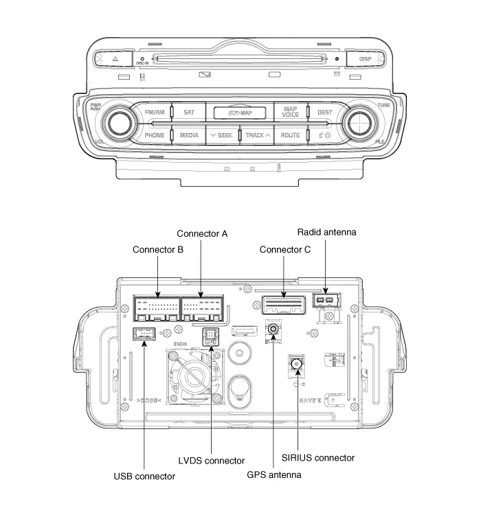
| Components |
| AVN (A/V & Navigation) Head Unit Connector |
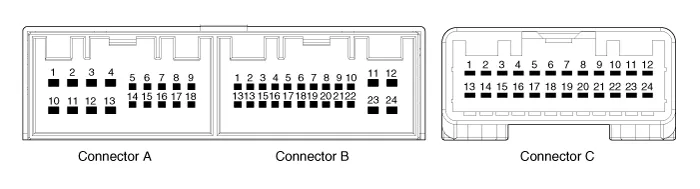
| No. | Connector A | Connector B | Connector C |
| 1 | - | MM CAN high | - |
| 2 | Back view camera video | - | - |
| 3 | Back view camera video ground | - | - |
| 4 | Back view camera power ground | Steer key | RS422 ground |
| 5 | SPDIF ground | - | RS422 Tx (+) |
| 6 | SPDIF (+) | - | RS422 Tx (-) |
| 7 | - | - | RS422 Rx (-) |
| 8 | Illumination (+) | AUX right | RS422 Rx (+) |
| 9 | R position | AUX ground | LVDS PDN |
| 10 | - | MIC (+) | - |
| 11 | Camera battery (+) | ACC | - |
| 12 | Navigation voice (-) | Battery (+) | Ground |
| 13 | Navigation voice (+) | MM CAN low | LVDS LOCK |
| 14 | Back view camera DETECT | - | EXT B/L ON |
| 15 | SPDIF (-) | - | RS485 Rx (+) |
| 16 | Door unlock | Speed | RS485 Rx (-) |
| 17 | Illumination (-) | Steer key ground | RS485 ground |
| 18 | Antenna power | - | RS485 Tx (-) |
| 19 | | - | RS485 Tx (+) |
| 20 | AUX DETECT | TMU voice (+) | |
| 21 | AUX left | TMU voice (-) | |
| 22 | MIC (-) | - | |
| 23 | Ground | Ground | |
| 24 | Ground | - |
Limitations Of The Navigation system GPS Signal Reception State As the GPS satellite frequency is received/transmitted in straight lines, reception may not work if hiding devices are placed on or near the GPS antenna or when traveling through the following locations.
Removal AVN Head Unit • Take care not to scratch the center fascia panel and related parts. • Ejact all the disc before removing the AVN head unit to prevent damaging the CD player''s load mechanism.
Other information:
Kia Cadenza YG 2016-2021 Service Manual: Parking Assist Sensor Repair procedures
Removal 1. Disconnect the negative (-) battery terminal. 2. Remove the rear bumper cover. (Refer to Body - "Rear Bumper Cover") 3. Disconnect the connector (A) from the parking assist sensor. 4. Pull out the sensor (A) by opening the sensor holder (B) out.
Kia Cadenza YG 2016-2021 Service Manual: General Safety Information and Caution
Instructions When Handling Refrigerant 1. R-134a liquid refrigerant is highly volatile. A drop on the skin of your hand could result in localized frostbite. When handling the refrigerant, be sure to wear gloves. 2. It is standard practice to wear goggles or glasses to protect your eyes, and gloves to protect your hands.
Categories
- Manuals Home
- Kia Cadenza Owners Manual
- Kia Cadenza Service Manual
- Battery Troubleshooting
- Steering System
- Schematic Diagrams
- New on site
- Most important about car
