Kia Cadenza YG: Steering wheel / Heated Steering wheel Schematic Diagrams
| System Circuit Diagram |
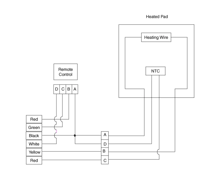

| Housing | Pin | Function | Wire color |
| Pad | A | GND | Back |
| B | HEATER | Yellow | |
| C | NTC+ | Back / Red | |
| D | NTC- | Back | |
| Remote control | A | GND | Back |
| B | BAT | Red | |
| C | LED | Green | |
| D | SWITCH | White |
Description When manually selected, the heated steering wheel system improves the thermal comfort of the driver by heating the steering wheel. Heated control unit Heated pad Specifications ItemSpecificationVoltage13.
Inpection 1. Measure a resistance of NTC and Heated pad. – NTC resistance(Black / Yellow, Black) - 10.0 kΩ ± 10% (25°C) – Heated pad resistance (Yellow, Black) - 1.
Other information:
Kia Cadenza YG 2016-2021 Service Manual: Start/Stop Button Repair procedures
Removal 1. Disconnect the negative (-) battery terminal. 2. Using a screw driver or remover, remove the center fascia lower panel (A). 3. Remove the in-car hose (A) and disconnect the connectors (B) from the heater & A/C control unit. 4.
Kia Cadenza YG 2016-2021 Service Manual: Lane Departure Warning System (LDWS) Unit Repair procedures
Removal 1. Disconnect the negative (-) battery terminal. 2. Remove the LDWS unit cover (A). 3. Remove the LDWS unit connector (A). 4. Remove the LDWS unit after widening the mounting clips. Installation 1. Install the LDWS unit. 2.
Categories
- Manuals Home
- Kia Cadenza Owners Manual
- Kia Cadenza Service Manual
- General Information
- Alternator Schematic Diagrams
- Engine Mechanical System
- New on site
- Most important about car
