Kia Cadenza YG: Steering wheel / Heated Steering wheel Description and Operation
| Description |
| Heated control unit |
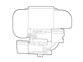
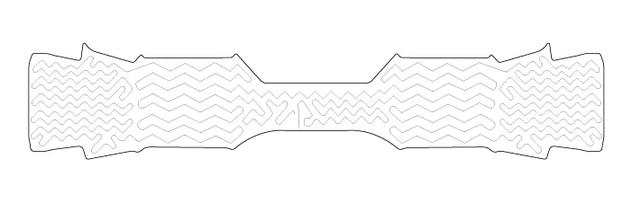
| Heated pad |

| Item | Specification | |||
| Voltage | 13.5 V | |||
| Heated pad resistance | 1.6 ~ 2.0 Ω ± 10% | |||
| NTC resistance | 10.0 kΩ ± 10% (25°C) | |||
| Current | 124A not over | |||
Removal 1. Disconnect the battery negative cable from the battery and then wait for at least 30 seconds. 2. Turn the steering wheel so that the front wheels can face straight ahead.
System Circuit Diagram Terminal Function HousingPinFunctionWire colorPadAGNDBackBHEATERYellowCNTC+Back / RedDNTC-BackRemotecontrolAGNDBackBBATRedCLEDGreenDSWITCHWhite
Other information:
Kia Cadenza YG 2016-2021 Service Manual: Description and Operation
Description System Overview The System offers the following features: – Human / machine interface through a 1-stage button, for terminal switching and engine start. – Control of external relays for ACC / IGN1 / IGN2 terminal switching and STARTER, without use of mechanical ignition switch.
Kia Cadenza YG 2016-2021 Service Manual: Auto defoging sensor Repair procedures
Inspection 1. Press the OFF switch more then 4 times within 2 seconds while pressing the MODE switch. DisplayFail description00Normal23Auto defog sensor OPEN24Auto defog sensor SHORT43Defog door potentiometer OPEN/SHORT44Defog door potentiometer * Diagnostic procedure refer to DTC code.
Categories
- Manuals Home
- Kia Cadenza Owners Manual
- Kia Cadenza Service Manual
- Components and Components Location
- Battery Troubleshooting
- Engine Mechanical System
- New on site
- Most important about car
