Kia Cadenza: Controller / Heater & A/C Control Unit (DATC) Components and Components Location
Kia Cadenza YG 2016-2025 Service Manual / Heating,Ventilation, Air Conditioning / Controller / Heater & A/C Control Unit (DATC) Components and Components Location
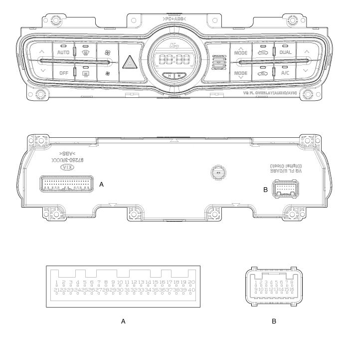
| Components (1) |
| [DIGITAL CLOCK TYPE] |

Connector Pin Function
| Connector | Pin No | Function | Connector | Pin No | Function |
| A | 1 | ILL + (TAIL) | A | 31 | PHOTO SENSOR (-) LEFT |
| 2 | SENSOR REF(+5V) | 32 | PHOTO SENSOR (-) RIGHT | ||
| 3 | HAZARD SIGNAL | 33 | HTD | ||
| 4 | ACC | 34 | REAR DEFOG S/W | ||
| 5 | MODE ACT''R (VENT) | 35 | K-LINE | ||
| 6 | MODE ACT''R (DEF) | 36 | - | ||
| 7 | MODE ACT''R F/B | 37 | - | ||
| 8 | INTAKE ACT''R (FRE) | 38 | - | ||
| 9 | INTAKE ACT''R (REC) | 39 | - | ||
| 10 | INTAKE ACT''R F/B | 40 | SENSOR GND | ||
| 11 | TEMP ACT''R DR (COOL) | B | 1 | GND | |
| 12 | TEMP ACT''R DR (WARM) | 2 | - | ||
| 13 | TEMP ACT''R DR F/B | 3 | DEF ACT''R (CLOSE) | ||
| 14 | TEMP ACT''R PS (COOL) | 4 | DEF ACT''R (OPEN) | ||
| 15 | TEMP ACT''R PS (WARM) | 5 | DEF ACT''R F/B | ||
| 16 | TEMP ACT''R PS F/B | 6 | HUMIDITY (PWM) | ||
| 17 | C_CAN HIGH | 7 | - | ||
| 18 | C_CAN LOW | 8 | IGN2 | ||
| 19 | DETENT OUT(+) | 9 | GND | ||
| 20 | ILL - (RHEO) | 10 | - | ||
| 21 | ION SIGNAL | 11 | BLOWER MOTOR (+) | ||
| 22 | CLEAN SIGNAL | 12 | FET (GATE) | ||
| 23 | IONIZER DIAGNOSIS | 13 | FET (DRAIN F/B) | ||
| 24 | MM_CAN HIGH | 14 | - | ||
| 25 | MM_CAN LOW | 15 | IGN1 | ||
| 26 | AMB SENSOR (+) | 16 | BATTERY | ||
| 27 | - | | | ||
| 28 | EVAP SENSOR (+) | | | ||
| 29 | ECV + | | | ||
| 30 | ECV - (GND) | | |
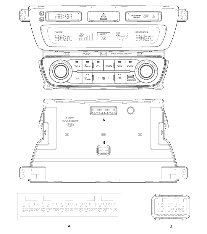
| Components (2) |
| [ANALOG CLOCK TYPE] |

Connector Pin Function
| Connector | Pin No | Function | Connector | Pin No | Function |
| A | 1 | ILL + (TAIL) | A | 31 | PHOTO SENSOR (-) LEFT |
| 2 | SENSOR REF(+5V) | 32 | PHOTO SENSOR (-) RIGHT | ||
| 3 | HAZARD SIGNAL | 33 | HTD | ||
| 4 | - | 34 | REAR DEFOG S/W | ||
| 5 | MODE ACT''R (VENT) | 35 | K-LINE | ||
| 6 | MODE ACT''R (DEF) | 36 | - | ||
| 7 | MODE ACT''R F/B | 37 | PAB_IGN1 | ||
| 8 | INTAKE ACT''R (FRE) | 38 | PAB CUT OFF SIGNAL | ||
| 9 | INTAKE ACT''R (REC) | 39 | SBR SIGNAL | ||
| 10 | INTAKE ACT''R F/B | 40 | SENSOR GND | ||
| 11 | TEMP ACT''R DR (COOL) | B | 1 | GND | |
| 12 | TEMP ACT''R DR (WARM) | 2 | - | ||
| 13 | TEMP ACT''R DR F/B | 3 | DEF ACT''R (CLOSE) | ||
| 14 | TEMP ACT''R PS (COOL) | 4 | DEF ACT''R (OPEN) | ||
| 15 | TEMP ACT''R PS (WARM) | 5 | DEF ACT''R F/B | ||
| 16 | TEMP ACT''R PS F/B | 6 | HUMIDITY (PWM) | ||
| 17 | C_CAN HIGH | 7 | - | ||
| 18 | C_CAN LOW | 8 | IGN2 | ||
| 19 | DETENT OUT(+) | 9 | GND | ||
| 20 | ILL - (RHEO) | 10 | - | ||
| 21 | ION SIGNAL | 11 | BLOWER MOTOR (+) | ||
| 22 | CLEAN SIGNAL | 12 | FET (GATE) | ||
| 23 | IONIZER DIAGNOSIS | 13 | FET (DRAIN F/B) | ||
| 24 | MM_CAN HIGH | 14 | - | ||
| 25 | MM_CAN LOW | 15 | IGN1 | ||
| 26 | AMB SENSOR (+) | 16 | BATTERY | ||
| 27 | - | | | ||
| 28 | EVAP SENSOR (+) | | | ||
| 29 | ECV + | | | ||
| 30 | ECV - (GND) | | |
| Components (3) |
| [UVO TYPE] |

Connector Pin Function
| Connector | Pin No | Function | Connector | Pin No | Function |
| A | 1 | ILL + (TAIL) | A | 31 | PHOTO SENSOR (-) LEFT |
| 2 | SENSOR REF(+5V) | 32 | PHOTO SENSOR (-) RIGHT | ||
| 3 | HAZARD SIGNAL | 33 | HTD | ||
| 4 | ACC | 34 | REAR DEFOG S/W | ||
| 5 | MODE ACT''R (VENT) | 35 | K-LINE | ||
| 6 | MODE ACT''R (DEF) | 36 | - | ||
| 7 | MODE ACT''R F/B | 37 | PAB_IGN1 | ||
| 8 | INTAKE ACT''R (FRE) | 38 | PAB CUT OFF SIGNAL | ||
| 9 | INTAKE ACT''R (REC) | 39 | SBR SIGNAL | ||
| 10 | INTAKE ACT''R F/B | 40 | SENSOR GND | ||
| 11 | TEMP ACT''R DR (COOL) | B | 1 | GND | |
| 12 | TEMP ACT''R DR (WARM) | 2 | - | ||
| 13 | TEMP ACT''R DR F/B | 3 | DEF ACT''R (CLOSE) | ||
| 14 | TEMP ACT''R PS (COOL) | 4 | DEF ACT''R (OPEN) | ||
| 15 | TEMP ACT''R PS (WARM) | 5 | DEF ACT''R F/B | ||
| 16 | TEMP ACT''R PS F/B | 6 | HUMIDITY (PWM) | ||
| 17 | C_CAN HIGH | 7 | - | ||
| 18 | C_CAN LOW | 8 | IGN2 | ||
| 19 | DETENT OUT(+) | 9 | GND | ||
| 20 | ILL - (RHEO) | 10 | - | ||
| 21 | - | 11 | BLOWER MOTOR (+) | ||
| 22 | - | 12 | FET (GATE) | ||
| 23 | - | 13 | FET (DRAIN F/B) | ||
| 24 | - | 14 | - | ||
| 25 | - | 15 | IGN1 | ||
| 26 | AMB SENSOR (+) | 16 | BATTERY | ||
| 27 | - | | | ||
| 28 | EVAP SENSOR (+) | | | ||
| 29 | ECV + | | | ||
| 30 | ECV - (GND) | | |
 Controller
...
 Heater & A/C Control Unit (DATC) Repair procedures
Inspection
Self diagnosis
1.
Self-diagnosis process
2.
How to read self-diagnostic code.
After the display panel flickers three times every 0.5
second, the corresponding fault code flicker ...
Other information:
Kia Cadenza YG 2016-2025 Service Manual: Thermostat Components and Components Location
Components 1. Water temperature control assembly2. Thermostat3. Water inlet fitting pipe ...
Kia Cadenza YG 2016-2025 Service Manual: Front Oil Seal Repair procedures
Replacement 1. Remove the crankshaft damper pulley. (Refer to Timing System - "Crankshaft Damper Pulley") 2. Remove the front oil seal (A). 3. Using SST(09231-3C100), install a new front oil seal. Do not reuse the front oil seal. &nbs ...
Copyright © www.kcadenzavg.com 2017-2025

