Kia Cadenza YG: Indicators And Gauges / Instrument Cluster Schematic Diagrams
| Circuit Diagram |

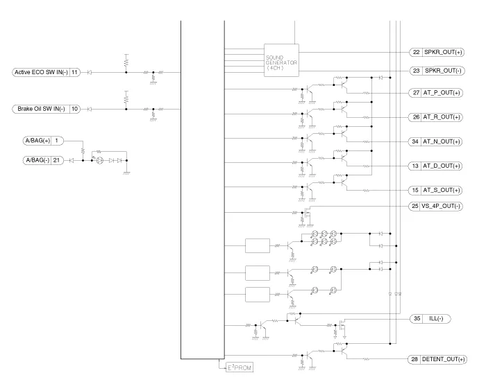


Components Connector Pin Information No.DescriptionNo.Description1Air bag (+)21Aig bag (-)2Trip switch (+)22Speaker output (+)3Cruise switch (+)23Speaker output (-)4Rheostat down switch (-)24Trip switch (-)5Rheostat up switch (-)25VS 4P output (-)6Oil pressure (-)26AT R output (+)7Washer indicator (-)27AT P output (+)8Battery charge (-)28Detent output (+)9H/SWHL indicator (+)29Immobilizer (-)10Brake oil switch (-)30MM CAN high11Active ECO switch (-)31MM CAN low12Driving mode switch (-)32C CAN low13AT D output (+)33C CAN high14Fuel (+)34AT N output (+)15AT S output (+)(AT)35Illumniation (-)16Fuel (-)36P ground17-37S ground18Glass status signal (-)38-19-39IGN 1 (+)20Illumination (+)40Battery (+)
Inspection Speedometer 1. Adjust the pressure of the tires to the specified level. 2. Drive the vehicle onto a speedometer tester. Use wheel chocks (A) as appropriate.
Other information:
Kia Cadenza YG 2016-2021 Service Manual: Troubleshooting
Troubleshooting Problem Symptoms Table Before replacing or repairing air conditioning components, first determine if the malfunction is due to the refrigerant charge, air flow or compressor. Use the table below to help you find the cause of the problem.
Kia Cadenza YG 2016-2021 Service Manual: Heater Unit Repair procedures
Replacement 1. Disconnect the negative (-) battery terminal. 2. Recover the refrigerant with a recovery/ recycling/ charging station. 3. When the engine is cool, drain the engine coolant from the radiator. 4. Remove the expansion valve cover (A).
Categories
- Manuals Home
- Kia Cadenza Owners Manual
- Kia Cadenza Service Manual
- Restraint
- Rail Pressure Sensor (RPS) Schematic Diagrams
- Emission Control System
- New on site
- Most important about car
