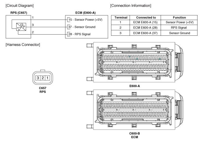
Kia Cadenza YG: Engine Control System / Rail Pressure Sensor (RPS) Schematic Diagrams
| Circuit Diagram |
Signal Waveform
Inspection 1. Connect the GDS on the Data Link Connector (DLC). 2. Measure the output voltage of the RPS at idle and various engine speed. ConditionOutput Voltage (V)Idle Approx.
Other information:
Kia Cadenza YG 2016-2021 Service Manual: Adaptive Front Lighting System Description and Operation
Description AFLS Unit(ECU) AFLS located in Cockpit Module is provided information of vehicle (steering wheel signal,vehicle speed, inclination of vehicle). Based on provided information , it calculates algorithm and adjust Low beam of H/Lamp. It transmits driving information by using LIN protocol, it is operated in Fail-safe reaction mode
Kia Cadenza YG 2016-2021 Service Manual: Repair procedures
Diagnosis With GDS 1. BSD system defects can be quickly diagnosed with the GDS. GDS operates actuator quickly to monitor, input/output value and self diagnosis. 2. Connect the cable of GDS to the data link connector in driver side crash pad lower panel, turn the power on GDS.
Categories
- Manuals Home
- Kia Cadenza Owners Manual
- Kia Cadenza Service Manual
- Emission Control System
- Alternator Schematic Diagrams
- Brake System
- New on site
- Most important about car
