Kia Cadenza YG: Engine Control System / Rail Pressure Sensor (RPS) Troubleshooting
Kia Cadenza YG 2016-2021 Service Manual / Engine Control / Fuel System / Engine Control System / Rail Pressure Sensor (RPS) Troubleshooting
| Signal Waveform |
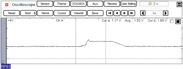
Specification Pressure [MPa (kgf/cm², psi)]Output Voltage (V)0 (0, 0)0.510 (102, 1450)2.520 (204, 2900)4.5
Circuit Diagram
Other information:
Kia Cadenza YG 2016-2021 Service Manual: Start/Stop Button Repair procedures
Removal 1. Disconnect the negative (-) battery terminal. 2. Using a screw driver or remover, remove the center fascia lower panel (A). 3. Remove the in-car hose (A) and disconnect the connectors (B) from the heater & A/C control unit. 4.
Kia Cadenza YG 2016-2021 Service Manual: Auto defoging actuator Repair procedures
Inspection 1. Ignition "OFF”. 2. Disconnect the connector of auto defog control actuator. 3. Verify that the auto defog control actuator operates to the defrost ON mode when connecting 12V to the terminal 3 and grounding terminal 7. 4.
Categories
- Manuals Home
- Kia Cadenza Owners Manual
- Kia Cadenza Service Manual
- Alternator Schematic Diagrams
- Restraint
- Battery Troubleshooting
- New on site
- Most important about car

Copyright © 2026 www.kcadenzavg.com - 0.0228